Posts

Showing posts with the label empennage

Elevator finally complete!

Image
OK, so I got the correct trim tab, and guess what? It had some damage! But, I managed to fix it, and get it installed. So finally the end of that ordeal. Also added the rivnuts to hold the trim tab servo access plate: The eight holes surrounding the opening, for the rivnuts, are undersized. So I will have to open them a little bit. But, they are quite close to the edge of the opening, so I will need to support the area when I drill. I'm doing this with clams a piece of wood, simple and effective (Two clamps were actually used, one on each side of the hole): All done: I also put on the other elevator tip: And I can now call the elevator finally done (for now)! Woohoo!

More Trim Tab Woes & Elevator Progress!

Image
Bad news first. That new, shiny, perfectly straight trim tab? Yeah, it's the WRONG PART! Apparently it was mislabelled as a left trim tab, when it is in fact a right one: The top 2 are my previous, old and busted ones, notice the shape and angle on the right, and the location of the holes for the control horn. The bottom one is reversed! So I guess I'll go ahead and get a *4th* one. But, not to worry, this hasn't stopped me from making good progress on the rest of the elevator: Getting the skin on just right was a bit of a challenge, but I'm quite happy with the result. I gotta say, placing it vertically sure helped: stand at the end, look down the edge, look at the ribs, etc. and adjust as needed. Doing this laying flat on a table would've been far more painful, having it to flip it over constantly (That trim tab is an old dented one, but for the purposes of fitting everything it works fine, it's not yet one permanently). I...

Elevator #2 Progressing!

Image
I re-started my elevator as I had botched the first one (entirely my fault). Here it is ready to be skinned: And I finally got a *perfect* trim tab, very very straight! Third time's the charm:

Rudder completed for now!

Image
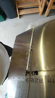
I've riveted the two skins on as much as I can for now until inspection, and made sure it fits with the VS well enough. It's a very quick test, but all looks well. I was especially curious about the spacing between the rudder and the VS up top, where the VOR antenna screws are. I may also add grounding screws for the lighting around there ... lots of room! Satisfying day :)

Rudder skin fit test

Image
All parts are deburred and primed and riveted together. My plans completely omit the installation of one part, so I nearly forgot to put in ... luckily it connects with the skin, so I quickly noticed the empty holes! Here is the result: Despite the slightly malformed parts, looks like everything should it nicely! I guess the fluting helped!

Rudder Prep Work

Image
Deburred all the rudder frame parts (i.e. all but the skins), and then primed. I consistently find parts with small "issues", which is getting tiresome. Today there was this rather thick rib with no curved bends that wasn't straight: Really seems like that shouldn't be, since there's no curvature, it should've remained flat through the manufacturing process ... looks like it was abnormally bent somehow. I did some fluting to it, hopefully that'll work out OK. And then a piece that again has some abnormal bends into it: (Note the right side in the picture, not straight at all). I tried the seamer to no avail ... I also clamped it down with a block, didn't change much ... Hopefully I'll manage to get it fitting OK.

Done VS for now, starting the rudder

Image
OK, I riveted the one side of the VS, and put it away for now: And pulled out the rudder bits and removed the plastic film:

VOR Antenna & VS Skin Fit

Image
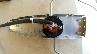
Was waiting on a few more parts! Connected the antenna to its coax cable, which took some figuring out because of this little looped wire that was completely in the way (Part of the "balun" I suspect): I riveted on a cable tie mount and used a cable tie to relieve the forces from the antenna connector itself, and added a bit of RTV silicone to make sure the cable never rubs against one of the mounting screws. Then mount the rib to the rest of the VS frame: Looking good! After making sure the coax was running down to the bottom of the VS nicely, I fitted the skin: Had to open up the antenna holes a bit to prevent rubbing, but everything else seems to fit nicely. Next to deburr, prime and rivet on one side of the skin (Keep the other side clecoed for inspection and to work on lighting wiring, something still to be figured out).

VS & VOR Antenna Work

Image
Had to take a break while my VOR antenna came in, as it was back ordered, so I took a couple of weeks off! Finally, it has arrived. I chose the  RAMI AV-12L . First, I put the frame together: Then, attach the doubler plate and the antenna to the top rib: Upside of this antenna, it's more affordable and less draggy than the obvious alternatives. Downside is, the 2 "rods" are not removable. This means that instead of holes to run them through, I need "slots". So I put those in and made sure to file and deburr everything. Once in place, I secured with the screws and locknuts: I also placed the rib in its spot and cut out the skin where needed: Not the best looking thing, since I had to notch it out, instead of holes. We'll see what we can do to beautify this when comes pain time. Finally, I ran the coax cable for the antenna through the ribs: Note the absence of wiring for lighting. Given my predicament with the lights, this ...

Skinning the horizontal stabilizer, and working vertically

Image
With the front spar issue fixed, I can move forward on the HS. It was the first assembly I started, and it is a relatively simple one, so I'm looking forward to being able to call that one complete. I ran the electrical wire for the trim, through the grommets, and the edge protection in the lightning hole, and now I proceed to skinning: Again, note how I work vertically. Things line up very nicely this way. No requirement to "get kinks out", to try and stretch the skin, or anything like that. I started with it lying on a table, but again, this part is NOT flat, and when I flipped it over to the other side, things were not looking as lined up as I'd hoped. The minute I put it up, thing fell into place quite nicely. You can see it's precariously sitting on some bits of 2x4's ... not super stable, but stable enough. I just don't leave it alone like that. This is actually the fairly common way to assemble these kinds of components. I suspect T...

The HS spar is fixed!

Image
Fits like a glove this time :)

Yet more elevator work!

Image
I got my HS and elevator parts in the same shipment, but since I got going on the elevator, I'll keep doing that! As you can see I found a neat way to work vertically. The empennage assemblies are not actually flat and tend to move/rock on a table top, which drives me nuts. So I let gravity do the work ... and I learn from other builders on other kits, where this kind of technique is more common.

Elevator challenges

Image
Not been having luck lately! First, settings the rivets int he control horn didn't work quite as planned. One stem ended up loose, and one ended up crooked. Because these are stainless steel rivets, forget about drilling them out in any accurate, simple fashion. So, new parts ordered! Secondly, the trim tab ended up warped. I think I may have bent it accidentally while trying to remove the plastic sheet from inside. Ordering new parts!

More elevator work

Image
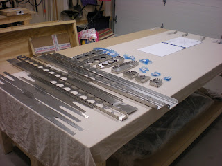
I've been prepping the elevator metal. Found a better way to get my parts to dry after priming, put some small nails into my custom built shelving unit, and voila! First, here are all the parts nicely laid out: Then here they are drying: And here I am putting the trim tab together:

Horizontal stabilizer wait and elevator/trim tab start

Image
Well its official, apparently the front HS spar has to be nice and tight, so TAF is sending me some new parts! In the mean time, I'm starting the elevator. And the first part is the trim tab, which requires shortened rivets. Here is how I did it: First, hammer out the mandrel. I did this with the bench vise set at juuust the right opening (sorry, some blurry pictures ahead): Then, place the rivet upside down in a piece of spare sheet metal with a hole in it, held with a clamp. This holds it in place upside down. Then used a cutting wheel to cut off about half of the rivet's length. Finally, deburr the work a little bit: Then, back in the vise to put the mandrel back in: Repeat 32 more times!

Misaligned holes, or rookie mistake?

Image
I have been riveting my HS, and have run into a bit of a snag: Note the bent metal. This is where the two front spar channels meet. I had some hole alignment issues on my first try, so I unclecoed and reclecoed everything, and things went better at first, and a number of rivets are indeed set: But then I noticed the above, possibly a little later than I should have. The remainder of the rivets to set on that side of the HS will not go in (See the two matching rows of clecoes below, on the flanges of the spar). Note how the "top" ones are set. There is some misalignment left, however small, and I can't proceed further without having to do some things I'm not sure about at this point. ​Thoughts so far: One solution i could contemplate: match-drill/ream the problematic holes, and just keep going. Once the two holes where the bend is situated are "used" (to attach to the airframe I presume), it might all end up solid enough. The holes ...

Horizontal stabiliser deburring & fluting completed!

Image
I have now completed the deburring and cleaning of the horizontal stabiliser. It went rather well. I won't document the process, as the internet does a fine job already. Some noteworthy points however: In some spots the protective film was not doing its job, leaving a white/milky surface. This is easily cleaned with isopropanol. The manufacturing seems to do a decent job of not leaving too many burrs, I run my fingers along edges and use files and other tools to remove the burrs I find, and only those: There are many other ways to deburr of course, notably sandpaper and deburring wheels, both of which I have ... so I will continue to experiment ... the files work nicely and precisely, but are maybe  a little slow. Then again, I'm not in a hurry! Ribs are also fluted! Finding ways to flute the small nose ribs without bending too much metal and create sharp edges is a little tricky, but luckily given their size, not much fluting is required anyways. Found a fe...

Empennage lighting

The empennage is a relatively simple thing, 4 surfaces (vertical and horizontal stabilizer, rudder, and elevator). It does however "contain" 2 systems: Electrical trim, and lighting. Lighting can be subject to regulation, and in Canada, is indeed, even on home-built aircraft. The rules are :  Standard 625 Schedule 1 - Position and Anti-collision Light Systems Not as stringent as the certified rules, but more stringent than US rules. As it turns out, the Sling 4 kit, as provided, does not let me meet these requirements. I will need to improvise. The big problem is the requirement to have a steady white light facing aft though 140 degrees, like this . Although there is an alternative solution of using two steady white lights on the wing tips, the way the lights mount on the Sling 4's wing tips, that won't work, as they will not provide the required projection. You can see why here . They angle forward and downwards somewhat. Even with white aft lighting on t...

Empennage unboxing

Image
Here is what an empennage kit looks like once opened: Basically, a packing list, a manual, and a bunch of parts! The contents are arranged in a number of sub-packages, which are either "assemblies" or "hardware", and I also have some "extras". For example, here is the rudder assembly as it comes out of the box: And with the contents spread-out for inventory taking: And here is what the hardware bags look like: As you can see, everything is nicely organised and packaged. Everything categorised by assembly, and each assembly being assembled as a unit, per the manual. So, the first thing in the empennage manual to be done is the horizontal stabiliser, so we'll pull out the "assembly" and "hardware" bags for that piece of airframe, and get cracking!

Empennage kit arrival

Image
My first kit, the empennage kit (Basically, the tail), has arrived! Tiny bit of damage on one corner of the box, but looks superficial ...