Posts

More elevator work

Image
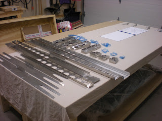
I've been prepping the elevator metal. Found a better way to get my parts to dry after priming, put some small nails into my custom built shelving unit, and voila! First, here are all the parts nicely laid out: Then here they are drying: And here I am putting the trim tab together:

Horizontal stabilizer wait and elevator/trim tab start

Image
Well its official, apparently the front HS spar has to be nice and tight, so TAF is sending me some new parts! In the mean time, I'm starting the elevator. And the first part is the trim tab, which requires shortened rivets. Here is how I did it: First, hammer out the mandrel. I did this with the bench vise set at juuust the right opening (sorry, some blurry pictures ahead): Then, place the rivet upside down in a piece of spare sheet metal with a hole in it, held with a clamp. This holds it in place upside down. Then used a cutting wheel to cut off about half of the rivet's length. Finally, deburr the work a little bit: Then, back in the vise to put the mandrel back in: Repeat 32 more times!

Misaligned holes, or rookie mistake?

Image
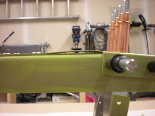
I have been riveting my HS, and have run into a bit of a snag: Note the bent metal. This is where the two front spar channels meet. I had some hole alignment issues on my first try, so I unclecoed and reclecoed everything, and things went better at first, and a number of rivets are indeed set: But then I noticed the above, possibly a little later than I should have. The remainder of the rivets to set on that side of the HS will not go in (See the two matching rows of clecoes below, on the flanges of the spar). Note how the "top" ones are set. There is some misalignment left, however small, and I can't proceed further without having to do some things I'm not sure about at this point. ​Thoughts so far: One solution i could contemplate: match-drill/ream the problematic holes, and just keep going. Once the two holes where the bend is situated are "used" (to attach to the airframe I presume), it might all end up solid enough. The holes ...

Cleaning and priming of horizontal stabiliser parts completed!

Image
Next step in empennage preparation was prepping the metal for priming, and then priming. I am electing to follow the recommendation from the factory to prime only mating surfaces. This is much easier than having to deal with fully spraying all the parts, which is a much more involved process I don't feel is entirely warranted for 6061-T6 aluminum, which is already quite corrosion resistant. Priming mating surfaces is also what Zenith aircraft recommends, on the same aluminum alloy, for corrosion protection, as can be seen in this EAA video . My approach: I am using Stewart System's EkoPrime primer product, instead of the Cortec VCI-373. This is mostly because I can't quite figure out how to source the Cortec in any convenient manner. The Stewart Systems products seem to have a good reputation, and are easily sourced via Aircraft Spruce. I am using a coloured product, in my case the Zinc Chromate Green. Many builders use the white version that turns clear after...

Horizontal stabiliser deburring & fluting completed!

Image
I have now completed the deburring and cleaning of the horizontal stabiliser. It went rather well. I won't document the process, as the internet does a fine job already. Some noteworthy points however: In some spots the protective film was not doing its job, leaving a white/milky surface. This is easily cleaned with isopropanol. The manufacturing seems to do a decent job of not leaving too many burrs, I run my fingers along edges and use files and other tools to remove the burrs I find, and only those: There are many other ways to deburr of course, notably sandpaper and deburring wheels, both of which I have ... so I will continue to experiment ... the files work nicely and precisely, but are maybe  a little slow. Then again, I'm not in a hurry! Ribs are also fluted! Finding ways to flute the small nose ribs without bending too much metal and create sharp edges is a little tricky, but luckily given their size, not much fluting is required anyways. Found a fe...

Empennage lighting

The empennage is a relatively simple thing, 4 surfaces (vertical and horizontal stabilizer, rudder, and elevator). It does however "contain" 2 systems: Electrical trim, and lighting. Lighting can be subject to regulation, and in Canada, is indeed, even on home-built aircraft. The rules are :  Standard 625 Schedule 1 - Position and Anti-collision Light Systems Not as stringent as the certified rules, but more stringent than US rules. As it turns out, the Sling 4 kit, as provided, does not let me meet these requirements. I will need to improvise. The big problem is the requirement to have a steady white light facing aft though 140 degrees, like this . Although there is an alternative solution of using two steady white lights on the wing tips, the way the lights mount on the Sling 4's wing tips, that won't work, as they will not provide the required projection. You can see why here . They angle forward and downwards somewhat. Even with white aft lighting on t...

Riveting decision

I'll spare you the suspense: I'm not going to do it. Here's why: From a strict engineering perspective, I shouldn't: The holes are over-sized, even for an over-size rivet. Rivet manufacturer says I should not do this. Even the clamping force doesn't seem to do enough to provide proper full grip. The hole does not "close in around the rivet" as I had hoped. As it turns out, the best-bet rivet for this application does NOT have an expanding shank. It really wants a tight fit from the get-go. My tests were done without reaming, which would enlarge the holes even more, and make the problems previously identified even worse. Being in a slightly too large hole, the rivet can set off-center, which is highly undesirable. I can't find any other combination of rivets/tooling that comes close to the over-sized CherryMAX approach. These rivets are quite expensive, would likely add 1000$+ to the project. I probably wouldn't be ahead financially in...